
Excavator Auxiliary Hydraulic Flow Configuration by Attachment: A Setup Reference for the 305 to 308 Class
I found the first one by accident, which is how most of these get found.
A machine came in for a weeping fitting at the base of the auxiliary circuit — a dime-sized dark patch on the belly pan, nothing urgent. The operator had his hands in his jacket pockets telling me it had worked loose over winter. I was already crouching, because the colour of that patch was sitting wrong in my head: light brown, thin, not the dark varnish a months-long seep leaves. So I pulled the fitting. Clean threads, torque felt right, no galling at the seat.
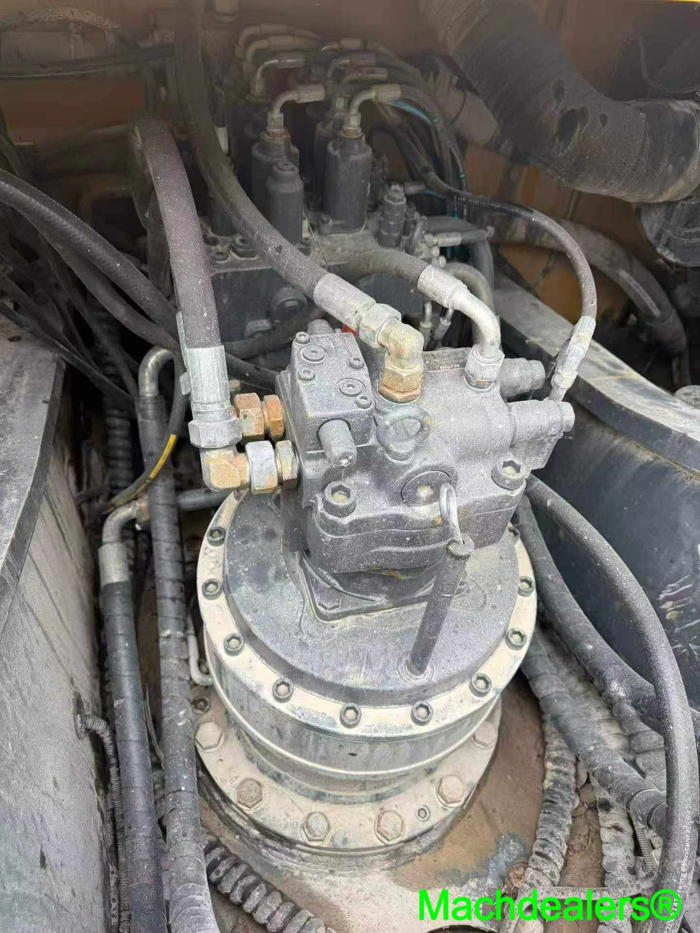
What changed my mind was the rod. I ran the flat of my hand along the cylinder rod through the full stroke and felt a faint drag at one point — not scoring, just a subtle stiffening, the way a door hinge tightens a degree before it squeals. That drag is heat. Seals that have cycled hot go slightly proud of their groove and then slightly soft, and you feel it in your palm before any gauge tells you a thing. The seal was already gone. The weep was just the first place oil could find daylight once the gland stopped holding shape.
Work it backwards. The heat had a cause, and it wasn’t the fitting. Probe on the return line at operating temperature with the machine doing real work in real ground: 8 to 12°C hotter than the same machine had run at the same ambient and duty cycle three months prior. That number is not dramatic. That number is the whole problem.
The design envelope for this class is 60 to 80°C continuous; past roughly 90°C you’re not operating a hydraulic system, you’re accelerating seal degradation from heat cycling at a rate that compounds. Every ten degrees over the top of the band roughly halves NBR seal life — roughly, because I won’t hand you a decimal I haven’t defended across enough machines. A rookie reads 60 to 80 as comfortable margin. A veteran reads 80 as a ceiling a 4,000-hour machine has been walking toward for years.
Then the part almost nobody reads. Before the temperature ever climbed, the auxiliary relief valve was talking — rhythmic chatter under continuous load, the valve cracking and reseating, a hard little tick under the engine note that gets dismissed as the attachment or the ground. Operators blame the tool. The tool is fine. The circuit is being asked for more flow than the relief setting and pump can deliver together, and the valve dumps the excess as heat into the oil. You might not have noticed that the chatter and the temperature rise are the same event described twice.
Relief settings across this range sit near 20.6 to 24.1 MPa, generation-dependent — the specific machine’s service manual is the only authority worth quoting when you’re actually setting one. What doesn’t vary is the behaviour.
Somewhere in that chain sits the proportional solenoid. A solenoid commanded wrong and one that’s failing look identical on a working machine. You get a lazy circuit, a hesitation, and the instinct is to suspect the valve when nine times out of ten it’s faithfully obeying a bad command sitting in the controller since the machine left the fleet.

Reading the Oil Like a Scene, Not a Sample
Crack the inspection port and hold the fluid in a clear jar at eye level. Light brown oil with tiny bubbles suspended in it, hanging rather than rising and breaking, is three problems stacked — read them in order or you’ll treat the wrong one.

[Expert Tip] Tilt the jar. Emulsified oil clings to the glass in a creamy film; entrained air won’t. One second separates a seal job from a suction-line job.
The return line filter bypass indicator is the most under-read signal on the machine. I’ve watched walkarounds where the tech checked blade, pins, fluid level and walked straight past it. It pops when the element is saturated and flow is bypassing filtration entirely — the machine is now circulating contaminated oil through every downstream component at full pressure. It doesn’t scream. It sits there extended, waiting. Four seconds to check on most machines in this class.
Also, don’t forget the lab sample everyone sends after a seal failure, which is nearly worthless: by then the oil has already been contaminated by whatever the seal was meant to keep out, so the profile reflects the failure event rather than the conditions that caused it. The sample I wanted was the one from ninety hours before. Nobody takes that one, because the machine was running fine.
Stop Reading That Monitor Number as Litres Per Minute
The number on that screen is not a flow rate. Not litres per minute, not any unit of volume at all.
On the software revisions I worked with across this class, the auxiliary page displays a commanded percentage of pump output — a slice of whatever the pump can deliver at that moment, not a fixed volume. Techs read “70” and think seventy litres. It’s seventy percent of something itself moving. Delivered flow shifts with engine RPM below the calibration point, oil temperature through internal leakage past worn components, and pump wear state. A machine at 4,000 hours showing an identical setting to one at 400 hours is not delivering identical flow, and that’s the one that catches buyers working off a screenshot.
The display never lies. It reports command faithfully. It’s the operator who supplies the assumption.
Honesty limitation, taken head-on: display logic and menu structure varied across software revisions through the 305 to 308 range, and I’ve been shown a screen that didn’t behave the way I expected because the machine ran a revision I hadn’t met. Verify against that specific machine’s manual. Not a forum post. Not mine.
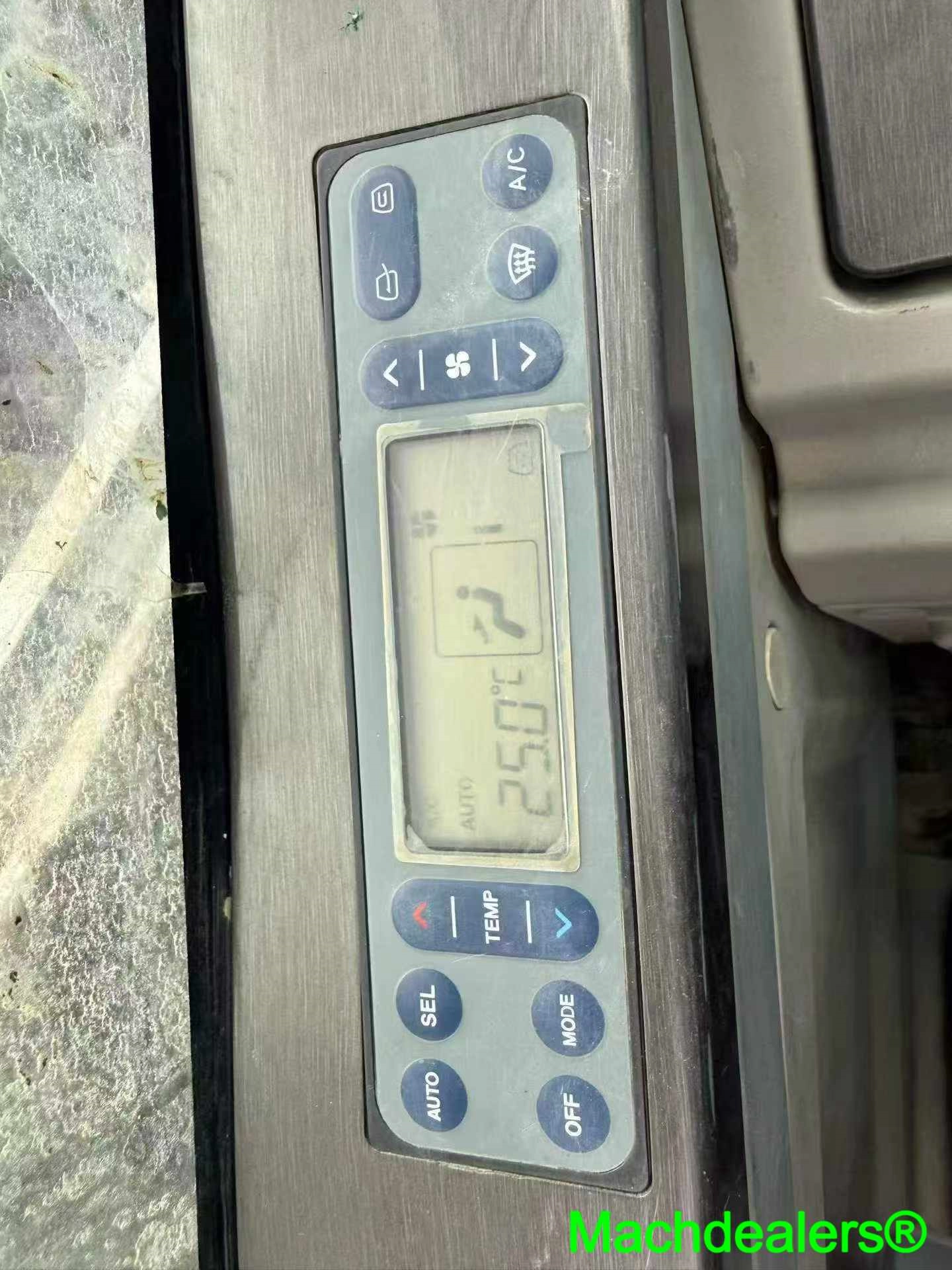
Walking the menu in prose, because a numbered list makes it look more standard than it is: settings branch off the main display, key on, engine off, down past machine information and calibrations to the attachment page, where two things matter — the flow assignment for the selected tool and the relief value sitting under it. Look at the flow figure and ask what attachment that number was written for.
What a Carryover Setting Looks Like
A machine sold out of a fleet with a thumb on it usually shows auxiliary flow in the middle-to-low band, and the seller calls it “set up for a thumb, all original, never touched” — true, and the exact reason the breaker you bolted on is starving. I crouched at the panel on the last one with the engine ticking down and heat still coming off the pump bay, two fingers flat on the tank: a pump loading unevenly transmits a fine buzz through the skin you feel better than you hear it.
[Expert Tip] Photograph the screen before you change anything. There’s no service history for a menu.
Why the 305 Class Behaves Differently From Its Neighbours
The 305 through 308 range gets treated as one family on paper and behaves like three machines in the dirt, and the reason sits in the auxiliary circuit.
Auxiliary flow here lands in roughly 60 to 90 L/min depending on generation and configuration, factory default commonly well below the maximum programmable figure. Ranges, deliberately — quoting one number across a range spanning several software and hardware revisions is the confident wrongness that cooks a breaker. The ceiling itself sits higher, comfortably past 100 L/min in some configurations, and that’s where trouble starts. I had a man tell me his machine was “rated for a mulcher” because the brochure number cleared the attachment’s minimum demand. What he’d done was bolt a tool that wants to live at the top of its band onto a circuit whose ceiling was the only thing that cleared it. Frankly speaking, that’s not margin. That’s a coincidence dressed as a specification.
Run a mulcher or breaker pinned at the top of its band for a full shift and the return oil comes back hot enough that the tank skin stings the back of your fingers at lunch. I still do that check — palm flat, two seconds — and if I pull my hand away faster than expected, the afternoon’s plan changes. Setting up mini excavator auxiliary hydraulic flow settings by attachment properly means treating that ceiling as a limit you stay clear of, not a target you aim at, and the multiplier nobody plans for is duty cycle: four minutes at the ceiling is a different thermal event from an hour there. What’s trickier is that the neighbours don’t all share pump architecture, so a setting that’s conservative on a 308 is reckless on a smaller frame carrying the same tool.
[Expert Tip] Size the attachment to roughly 80–85% of the programmable ceiling. The margin you leave is the thermal headroom that decides whether your seals see two thousand hours or six hundred.

The reference I keep open on the bench for the machine I see most — the cat 305 excavator settings log, cross-referenced against observed failures rather than factory tables — exists because borrowed numbers cost me a season before I started writing my own down.